Using Hot Wires / Snap Circuits with Raspberry Pi
It's Friday!! Time for some fun!
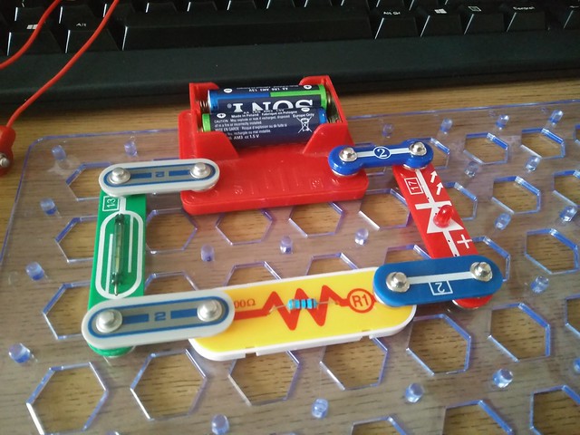
Hot Wires / Snap Circuits are simple circuit building blocks that are used to teach electronics to small children. They use press studs, similar to those used on coats, to connect the components, which are encased in a plastic shell meaning that small hands can't easily break the components.
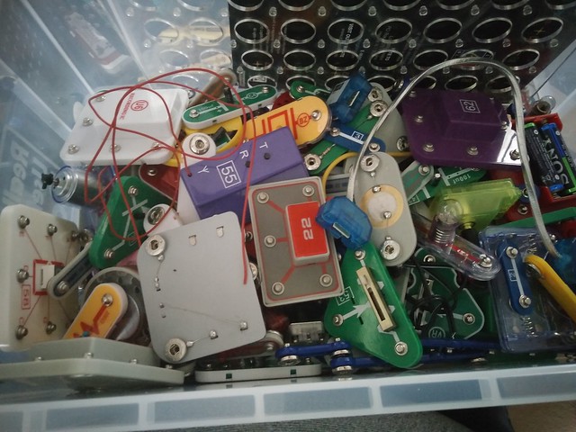
I've used them quite a lot at Blackpool Raspberry Jam as some of our younger children want to build rather than code.
I recently...well ok November 2016, received some of these wires...
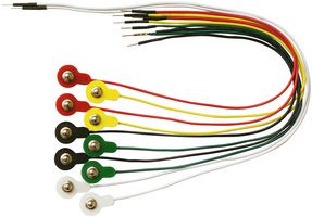
They are called "Snap to pin" and are used to convert the press stud connection to a breadboard compatible male jumper wire.
So armed with these wires and a "spare" (LOL) hour I made a simple circuit to illustrate how they can be used with any model of the Raspberry Pi and programmed two ways. Using Scratch and Python, with GPIO Zero.
Hardware Setup
I used
- 100 Ohm resistor (R1)
- Red LED (Piece 17) Note that the Red LED already has a 100 Ohm resistor soldered to the LED, but as we are teaching the right way to make a circuit, use the additional resistor to promote best practice
- Momentary Switch (S2)
- 2 x 2 Bridge Connector
- 3 x Snap to pin connectors (Black, Red and Yellow)
- 3 x Male to Female Jumper wires
- Any model of Raspberry Pi, I used a Zero W
- The usual accessories to control your Pi
Values in () are the Hot Wires part number.
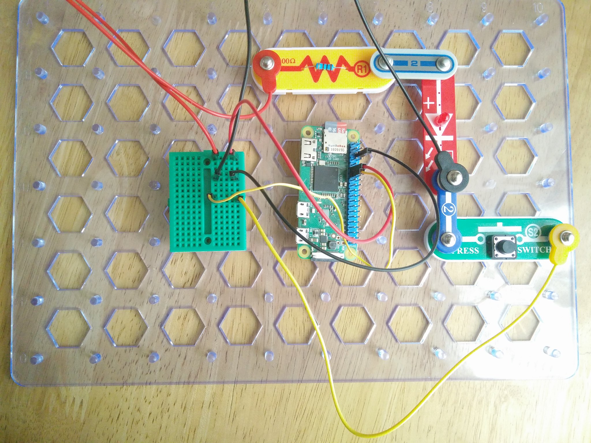
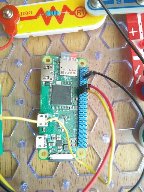
So for the red, black and yellow snap to pin wires, you can see in the picture that they are connected to the Hot Wires pieces and then connected to a breadboard.
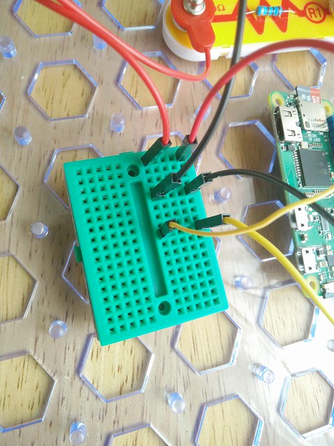
I then used the male to female jumper wires to connect the breadboard, and in turn the Hot Wires components to the GPIO of the Raspberry Pi. Note that I maintained colour coding for easy reference...and because I am a little OCD about that.
For reference
| Wire Colour | GPIO |
|---|---|
| Red | 17 |
| Yellow | 27 |
| Black | Ground |
So our Red wire connect the Red LED to GPIO 17 on our Raspberry Pi via a resistor.
The Yellow wire connect one side of the momentary switch / button to GPIO 27.
The black wire is connected to any Ground pin on the Raspberry Pi and to the Ground pin (Cathode) of our LED and to the other side of our momentary switch.
Here is a quick diagram that shows the position of the pins. Pin 1 is the pin nearest your SD card on every model of Pi.
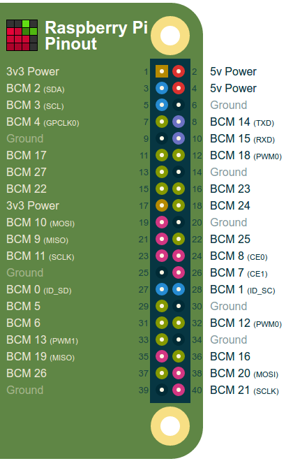
The awesome pinout.xyz from Gadgetoid!
So with the hardware built, power up your Pi and open Scratch!
Scratch
The basics of this project are based upon this worksheet from the Raspberry Pi Foundation
For our project we need to write the following code.
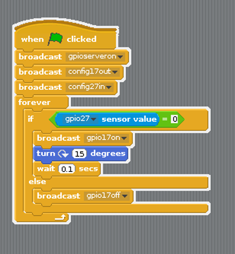
- We start by using a When Green Flag Clicked block from Control.
- Then we create three broadcasts, you can find this block in Control but you will need to create the text inside the block for each broadcast. Our first broadcast will turn on the server that enables Scratch to talk to the GPIO. The second and third configure pins 17 and 27 to be an output (for our LED) and an input (for the momentary switch)
- Now click on the Green Flag, located in the top right of the screen, this will enable the GPIO server and setup our GPIO pins. Then press the red stop button, also in the top right.
- Still in the Control palette we drag the Forever block over and place it under the broadcasts.
- We now need an If..Else block from Control, place it inside the loop.
- Now grab a __ = __ from Operators and place it in the space next to If.
- Go to Sensing palette and look for Sensor Value, left click on its drop down and you should see gpio27, this is our momentary switch. Change the sensor value block so that it reads gpio27 sensor value then drag it into the first space of our __ = __ block.
- In the second space type in the number 0. Now this block will compare the value that our momentary switch reports against the number 0. In other words when the switch is pressed its value changes from 1 (on) to 0 (off).
- If the button is pressed we turn gpio17on using another broadcast (Control palette).
- We also use turn from Movement to turn the cat sprite on our screen.
- Next we use wait from the Control palette to slow the rate that our cat spins at.
- We now move to our code for else and here we use a broadcast to turn off the LED gpio17off
So that's the code. Click on the green flag to run and watch your LED come to life and spin the cat!
Python 3 GPIO Zero
I also created a sample script in Python 3 using Ben Nuttall's great GPIO Zero library
The wiring is exactly the same as Scratch.
Here is all of the code. I edited and ran the code using Python 3 editor, found in the Programming menu.
from gpiozero import LED, Button
from time import sleep
led = LED(17)
button = Button(27)

while True:
    if button.is_pressed:
        print("LED Activated")
        led.on()
        sleep(0.1)
    else:
        print("LED Deactivated")
        led.off()
        sleep(0.1)
Essentially it works by using a loop and a conditional test. If the button is pressed, then the LED is turned on and we print something to the Python shell for debugging. If the button is not pressed then the LED is turned off and again we print to the Python shell.
Conclusion
Hot Wires / Snap Circuits and Raspberry Pi are a wonderful way to hack electronics projects to life, no matter how old the person may be.
Using a magnet to control a reed switch that turns on an LED.